Design of Flat Slab Using Is 456 Excel
"PLASTIC VOIDED SLAB TECHNOLOGY"
Project Report submitted in partial fulfillment of the
Requirement for the award of degree of
Bachelor of Engineering
In
Civil Engineering
Project members
EJAZ MEMON
HATIM JAWADWALA
MAYURI SANKHE
DILIP KEWAT
Under the guidance of
Prof. Faizan Shaikh
Chapter 1
Introduction
1.1 INTRODUCTION
When designing a reinforced concrete structure, a primary design limitation is the span of the slab between columns. Designing large spans between columns often requires the use of support beams and/or very thick slabs, thereby increasing the weight of the structure by requiring the use of large amounts of concrete. Heavier structures are less desirable than lighter structures in seismically active regions because a larger dead load for a building increases the magnitude of inertia forces the structure must resist as large dead load contributes to higher seismic weight. Incorporating support beams can also contribute to larger floor-to-floor heights which consequently increases costs for finish materials and cladding.
A new solution to reduce the weight of concrete structures and increase the spans of two-way reinforced concrete slab systems was developed in the 1990s in Europe and is gaining popularity and acceptance worldwide. Plastic voided slabs provide similar load carrying capacity to traditional flat plate concrete slabs but weigh significantly less. This weight reduction creates many benefits that should be considered by engineers determining the structural system of the building.
Plastic voided slabs remove concrete from non-critical areas and replace the removed concrete with hollow plastic void formers while achieving similar load capacity as solid slabs. Voided slab principles have been applied in different applications dating back to the early 1900s. This report examines the design process of plastic voided slabs. The principles behind plastic voided slab systems are presented. A parametric study of two-way flat plate reinforced concrete slabs and plastic voided slabs with the same design constraints is discussed. Before plastic voided slabs can be fully understood, a thorough knowledge of flat plate reinforced concrete slabs- behavior, failure mechanisms, design, and limitations- is critical.Traditional flat plate reinforced concrete slabs by describing how the slabs are constructed and resulting advantages and disadvantages of this construction. The design procedure and failure mechanisms for solid slabs are also described. The principles of using voids in slabs have been applied in various applications for many years.
The development of plastic voided slabs is presented in Chapter 4, while applications of plastic voided slabs are presented in Chapter 5. The design process for plastic voided slabs is discussed in detail in Chapter 6. Chapter 7 contains the results and conclusions of a comparison study that compares two-way flat plate reinforced concrete slabs to plastic voided slabs. The parametric study consists of four different designs for each slab type. The four slab designs are bays with dimensions of 30' by 27' (9m by 8m), 30' by 23' (9m by 7m), 27' by 23' (8m by 7m) and 23' by 17' (7m by 5m). The purpose of the study is to compare the design of a plastic voided slab to the design of a traditional two-way flat plate slab.
1.2 LITERATURE REVIEW
A significant amount of research work on various aspects of plastic voided slab has been published by many investigators. Some papers are briefly described below,
1.2.1 Roberto Il Grande
He is developed and patented a new system of hollow formers, in order to decrease the transportation costs (and CO2 production). The U-Boot formwork is a modular element made of re-cycled plastic for use in building lighter structures in reinforced concrete cast at the work-site.The biggest advantage of U-boot is that it is stackable. A truck of U-boot® means approximately 5000 m2 of slab, once hollow formers are laid down at building site. The second innovation is the shape: U-boot creates a grid of orthogonal "I" beams, so the calculation of the reinforcement can be effected by any static engineer according to Eurocode, British Standards or any local standard.
1.2.2 Schnellenbach-Held M., Ehmann S., Pfeffer K.
They wrote that an Bubble deck slab is the slab in which some amount of the concrete is replaced by the plastic hollow bubbles which are made by the waste plastic material, which reduces the self-weightofthestructure.The main effect of the plastic sphere is to reduce the dead load of the deck by1/3 in compare to solid slab having same thickness without effecting its deflection behavior & bending strength It locks spheres between the top and bottom reinforcement meshes, thereby creating a natural cell structure, acts like a solid slab. The slab is cast with the same capabilities as a solid slab, but with considerably lesser weight due to elimination of excessive concrete. Currently, this innovation technology has been applied to a few hundred residential high rise buildings, and industrial floor slab due to limited understandings. For this investigation, the structural behaviour of Bubble Deck under various condition will be studied in order to gain an understanding on this few technique and to compare it to the current slab system. This technology will then be applied to create lightweight bridge deck since a significant portion of the stress applied to a bridge comes from its own self-weight. By applying the knowledge gathered during the behaviroal analysis. Modular deck components for pedestrian bridges that is notably lighter but comparable in strength to typical reinforcement concrete section will be designed.
This floor system is designed to reduce the strength to weight ratio of typical concrete slab.it replaces or removes concrete from center of slab,where not or less useful.in place of that concrete,this design system uses hollow HDPE spheres to decrease the dead load of concrete floor.however it also reduces the slab resistance to fire and shear.
1.2.3 Jorgen Breuning
He studied that locks ellipsoids between the top and bottom reinforcement meshes, thereby creating a natural cell structure, acting like a solid slab. For the first time a hollow biaxial slab is created with the same capabilities as a solid slab, but with considerably less weight due to the elimination of superfluous concrete. Design of this type of the slab is based on the euro and the British codes.
1.2.4 A.Churakov
He observed that the hollow slabs are prefabricated, one-way spanning, concrete elements with hollow cylinders. Due to the prefabrication, these are inexpensive, and reduce building time, but can be used only in one-way spanning constructions, and must be supported by beams and/or fixed walls. The slab has been especially popular in countries where the emphasis of home construction has been on precast concrete, including Northern Europe and socialist countries of Eastern Europe. Precast concrete popularity is linked with low-seismic zones and more economical constructions because of fast building assembly, lower self-weight (less material), etc.
1.2.5 Neeraj Tiwari zafar
He had presented a paper.This presented a study on the Bubble Deck slab is a newly designed slab made by reinforcement mesh, hollow HDPE ball, reinforcement mesh again at bottom.it is based on the patented integration technique thai is the connection of steel and air. It is a hollow deck in which HDPE sphere ball acte the purpose of reducing concrete that has no carrying effect
Chapter 2
One - Way and Two – Way Reinforced Concrete Slab
Concrete was first used by the Romans for construction as early as 300 BC because it allowed for more flexibility in design than masonry construction, which was standard for large buildings at the time. Concrete has remained a popular building material, although the composition and construction method of concrete has changed minimally. However, over 2500 years, the most significant change to concrete has been the addition of steel reinforcement to increase concrete strength in tension. In common design practice, the concrete is designed to resist compressive force induced into a member, while reinforcing steel is designed to resist tensile forces. If needed, steel can be added to the compression region of a reinforced concrete member to help resist compressive forces, but concrete is not relied upon to resist tensile forces in the tension region.
The addition of reinforcing steel in the tension regions of concrete led to modern concrete construction. Reinforced concrete members have smaller dimensions than non-reinforced concrete members. Concrete slabs benefit greatly from the addition of reinforcing steel, as slabs can now be measured in inches rather than feet. This section reviews modern two-way flat plate, reinforced concrete slab construction, including advantages and disadvantages, as well as describing the design process for flat plate slabs.
2.1Solid Slab Types
Concrete slabs vary by type of frame construction. In steel frame buildings, concrete slabs often consist of a few inches of concrete placed over the top of steel deck. In precast concrete frame buildings, the slab is a topping slab, a few inches of concrete placed over a precast floor member such as a hollowcore plank. These slabs are supported by the hollowcore plank unless they are composite slabs. In cast-in-place concrete frame buildings, slabs are a few to several inches thick, depending on span, and can be cast with or without floor beams. Slabs in concrete frame buildings are the focus of this report.
Concrete slabs are typically classified as one-way or two-way systems based on the span lengths ratio in the two principal horizontal directions. Depending on the span length ratio, the flexural stiffness of the slab, solid reinforced concrete slabs are typically designed as either oneway or two-way slabs.
A one-way slab typically has a span ratio greater than 2. One-way slabs are designed as if they span in only one direction. The slab spans to beams and depending on reinforcement placement spans continuously over multiple bays. These slabs are designed as one-foot wide sections that transfer loading in only one direction. Reinforcement is designed to resist flexure in the short direction, perpendicular to the beams. Typically, the long direction, parallel to the beams, is lightly reinforced, meeting temperature and shrinkage resistance requirements.
one-way slab construction can lead to deeper structural members and larger floor-to-floor heights.
Two-way reinforced concrete slabs typically have span ratios less than 2 and are designed to span in two directions. Two-way slab systems come in many forms: flat plates, flat slabs, waffle slab, and two-way slab with beams. Flat plates, slabs with uniform thickness throughout, are typically used for lighter loads and shorter spans, 15 feet to 25 feet (4.6m to 7.6m). Flat slabs are used for higher load conditions, typically superimposed loads greater than 100 psf (4.8kPa) and longer spans, 25 feet to 35 feet (7.6m to 10.7m). The slabs of a flat slab system are not a constant thickness throughout- drop panels, thickening of the slab, at column locations are provided to transfer shear. These are less common today since more labor is required and the formwork costs are higher than the flat plate system. Waffle slabs are used for longer spans, 30 to 45 feet (9m to 13.7m). The slab thickness of the waffle slab is controlled by the required depth to transfer shear. The middle third of the span does not require this flexural stiffness; therefore to lighten the self-weight of the system, portions of the slab are reduced. The waffle slab is also known as a two-way pan-joist system. The two-way slab with beams incorporates the use of beams and girders, although two-way slabs can be supported only by columns and walls. Reinforcement for two-way slabs must be designed to resist flexure in both directions. Two-way slab design is more time intensive than one-way slab design as additional steps and checks are required in order to ensure proper design for the behavior of the system. Two-way slabs that do not use beams are shallower than two-way slabs with beams. With lighter loads and shorter spas, flat slabs lead to smaller floor-to-floor heights, thus reducing finish materials as 5
2.1.1 Solid Flat Slab Advantages
Solid flat slabs have many advantages related to load carrying capacity as well as the affect using flat slabs can have on the design of the whole building. Solid flat slabs are typically used to transfer up to hundreds of KN per square meter of load depending on slab thickness and span. In this type of design, no support beams or girders would be needed as the slab would be capable of spanning between columns with proper reinforcement detailing
One of the biggest advantages for a two-way flat slab compared to one-way slabs or two-way slabs that transfer load to beams and girders is that floor-to-floor heights are generally smaller for flat slabs. When no beams and girders are present, the structure occupies far less space, as much as a foot less at each floor. In a multi-story building, this can lead to several feet being reduced from the height of the overall building. Reduced building height allows for many different types of savings including less finish material such as
2.1.2 Solid Slab Disadvantages
Solid reinforced concrete slabs are well understood and accepted in structural engineering, but they are not without disadvantages. These disadvantages must be considered alongside the advantages when choosing a slab system for a building. Some disadvantages of solid concrete slab construction are presented in this section include the use of formwork and the large mass associated with solid slabs.
Whether a slab is designed as a one-way slab or a two-way slab, large amounts of formwork are needed to frame the slab until the concrete can harden. One-way slabs also require formwork for the beams used to support the slab. Placement and removal of formwork is labor intensive. The cost of labor is one of the driving factors in construction costs and time spent installing and removing formwork increases project costs. In addition to cost concerns, formwork can have sustainability concerns. Many types of formwork can be used for slab construction, such as metal, plastic, or wood.
2.2 Slab Type
As mentioned, two types of solid slabs are in existence: one-way and two-way. One-way slab design is far simpler than two-way slab design, but one-way slabs have shorter span limits which can limit their utility. One-way slabs depend on the use of intermediate beams for support. Since two-way slabs can be designed without intermediate beams, building design can necessitate the use of two-way slabs in order to minimize floor-to-floor height by avoiding beam usage. Determining the type of slab to design is one of the early decisions to be made in the solid slab design process.
The decision to use a flat plate or flat slab is based on a number of considerations. First, in order to use a two-way slab of any type the bays (the area between columns) must be relatively square as the ratio of the length of the long side to the length of the short side must be less than 2. In addition to considering the span ratio, the length of the span must be considered. Flat plates and flat slabs are most economical for spans between 15 feet and 35 feet (4.6m and 10.7m). For spans over 35 feet (10.7m), the slab must be several inches thick and it is often more economical for the design to incorporate beams and girders and use a thinner slab. If the span ratio and span length fall within the acceptable limits, the next design decision is whether to use a flat plate system or a flat slab system. As mentioned, flat plate slabs have uniform thickness but flat slabs do not. A flat slab usually has a thickness across most of the slab that is adequate to resist deflection and beam shear, which is discussed later in this chapter, while a drop panel is used near the column that adds thickness to the slab at that location to resist punching shear, which is also discussed later in this chapter. Columns with smaller bays have lower punching shear loads than columns with larger bays under the same superimposed load. Therefore, smaller bays are less likely to need additional thickness to resist punching shear, allowing flat plate systems to be used. Flat plates can be used for larger bays, but it may be more economical to incorporate a drop panel rather than increasing the slab thickness across the entire ba
Chapter 3
Voided Slab And Historical Application
Voided slabs attempt to utilize the positive aspects of concrete slab construction while minimizing the negative attributes of solid slabs by lightening the self-weight of the structure. This section discusses the concept of voided slab construction and reviews a number of historical applications of voided slabs.
3.1 Voided Slab Construction
Voided slab construction removes concrete in locations of the slab that are less critical to resist the applied loads. Removing concrete from the slab interior while maintaining overall depth of the section allows for comparable utility in most applications as the section modulus and stiffness are roughly equivalent to a solid slab, but the self-weight of the section is greatly reduced. This reduction has many benefits.
3.2 Historical Applications of Voided Slabs
Voided slabs are not a new construction method. Variations of voided slabs have been utilized for centuries. Though voided slabs principles were used centuries ago, many different types of voided slab systems were developed in the 1900s. This section briefly introduces and reviews various voided slab systems that were commonly used prior to modern construction.
3.2.1 The Pantheon
One of the oldest and most well-known uses of voided slabs occurred in ancient Rome when the Pantheon utilized voided slab concepts in its spectacular dome. The dome consists of numerous coffers which are voids on one side of the slab, often referred to as a waffle slab. The coffers remove material, thus reducing the overall weight of the slab. This concept is a key factor in the longevity of the Pantheon dome. The dome has a diameter of 142 feet (43.3m) but was constructed of concrete without reinforcement, making it highly susceptible to cracking (Gibson, 2012). Since the dome is inherently weak, it must be as light as possible to ensure it can support its own weight. Voids on the interior side of the dome allow for the reduced weight necessary for proper functioning of the dome. Since construction of the Pantheon, waffle slabs have been used on countless buildings for decorative purposes and structural considerations.
3.3 Different Types of System
3.3.1 Miller Precast System
n early type of precast hollow floor system was developed in 1929 by the Precast Floors Corporation of New York. The system was called the Miller Precast System. The Miller System consisted of 6-, 8-, or 10-inch (15cm, 20cm, or 25cm) deep by 12-inch (30.5cm) wide sections of concrete that were hollow in the middle (Stuart, 2008). The precast units were shipped in three segments that were aligned and supported on temporary shoring on site. The center segment came in standard lengths, while the end segments were constructed in custom lengths to allow for each specific location. Reinforcement was contained in the top and bottom portion of each segment and protruded out each end to be cast together after placement was finalized. A field-cast topping was applied to the units to contain additional reinforcement and provide continuity across beams. The Miller System was able to span larger distances than conventional one-way slabs because of its lower self-weight. Figure 3-1 shows a section through a Miller system unit, while Figure 3-2 shows an isometric of Miller system units prior to being joined.

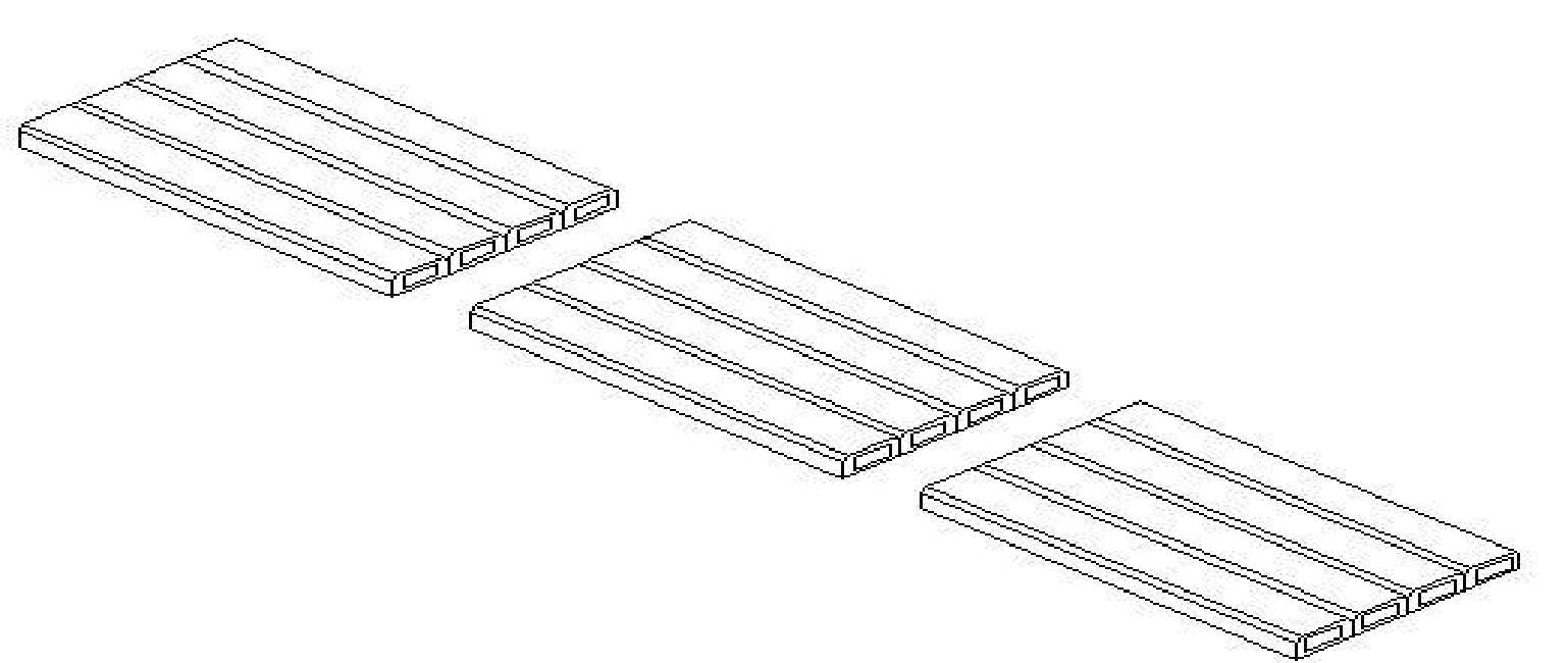
Figure 3-1: Miller System
3.3.2 Porete Floor System
The Porete Floor System was similar to the Miller System, consisting of hollow formed precast sections ranging from 4 to 6 feet (1.2m to 1.8m) in length (Stuart, 2008). Multiple sections could be combined into one long section by adding reinforcement in the topping slab. The Porete System could span 10 to 25 feet (3m to 7.6m) after temporary formwork was removed.
3.3.3 Precast Roof System
A third system, called the Pyrobar Precast Roof System, offered 4- to 6-inch (10cm to 15cm) Pyrobar deep hollow-core sections with widths of 12- to 18-inches (30cm to 45cm) and lengths of up to 6.5 feet (2m) that could be combined to form longer members (Stuart, 2008). The leading component all three systems was voids in the slab. The lighter self-weight allowed for long spans, while overall depth of the units allowed for necessary strength.
3.3.4 F&A System
Another type of voided slab system, referred to as the F&A System, was utilized in the 1950s. The F&A System combined precast concrete T-joists, hollow concrete blocks, and concrete topping to form a slab with high strength but low weight (Stuart, 2008). Hollow concrete blocks spanned between the T-joists were inverted so that the blocks could rest on the joists. Concrete was then poured on top of the assembly and acted compositely with the joists.
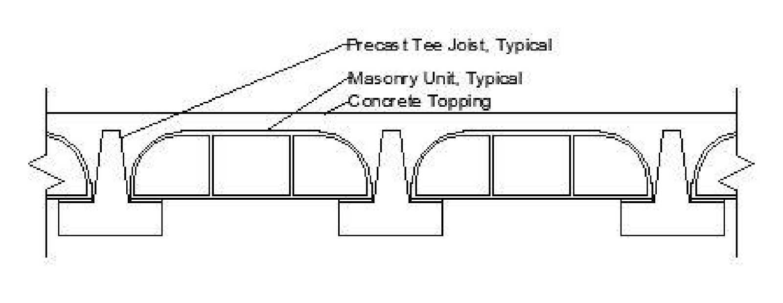
Figure 3-2: F&A System
Chapter 4
Voided Slabs Using Plastic Voids
Plastic voided slab systems are an alternative to traditional concrete slab construction. Plastic voided slab systems are significantly lighter than solid concrete slabs while maintaining the ability to have large spans. Slabs are lighter because less concrete is used in voided slab construction than traditional slab construction. This section discusses how plastic voided slabs are constructed and how lighter weight and larger spans affect building design.
4.1 Construction
Depending on the manufacturer, plastic voided slab systems are constructed by two primary methods: a filigree method in which part of the system is precast off site, and a method in which the entire system is constructed on site. Both methods use the same three basic components. In both methods, the main component is the plastic void. These voids are often spherical, hollow, and made of recycled plastic. The voids allow the slabs to be lighter than traditional concrete slabs since the voids are nearly weightless and replace concrete in the center of the slab. The next main component is the steel cage. Steel reinforcement is added to resist flexure for the slab, but a cage of thin steel is also used to hold the voids in place, keeping them in the center of the slab. The third main component is the concrete, which surrounds the voids and forms the slab. The concrete ultimately determines slab strength. Though both methods use each of these components, the two methods use different approaches.
4.2 Plastic Voided Slab Systems
Plastic voided slab systems were first introduced in Europe in the 1990s. Since that time, many European companies have patented their own systems. As a result, most uses of plastic voided slabs have occurred in Europe. Two plastic voided slab brands, BubbleDeck and Cobiax, have also been utilized in the United States. These two brands are the primary focus of this report, but this section briefly reviews all major brands and the slight differences that exist between them.
4.2.1 Bubble Deck
BubbleDeck is one brand of plastic void system which uses a precast filigree method to form voided slabs. In this method, the voids are assembled in steel cages and then concrete is poured to a height part way up the voids (Nasvik, 2011). The slab panels (filigree) are typically eight feet (2.5m) wide and thirty feet (9m) long. The filigree are then transported to the construction site and lifted in place by crane. Once in place, the top layer of concrete is placed, covering the voids and completing the slab. Wire trusses run between the precast and cast-in-place layers of concrete to ensure that the two layers bond properly.
4.2.2 Cobiax
Cobiax is another major brand of plastic void system. As compared to the BubbleDeck filigree system, Cobiax systems are an on-site application. When using Cobiax, workers first must use deck forms to form the bottom of the slab (Nasvik, 2011), and the bottom layer of reinforcing steel must also be placed. The voids arrive at the site bundled in steel wire cages which can be altered to fit the particular application, but the void bundles are secured to the reinforcement steel. After the bundles are in place, the top layer of reinforcement can be placed. Concrete is then placed in two lifts. Similar to the filigree method, the first lift covers the bottom reinforcement and a portion of the voids and holds the voids in place as the concrete becomes stiff. The second lift is poured after the first lift is stiff but still fresh, finishing the slab. This method requires more formwork and on-site labor than the BubbleDeck filigree method, but requires less transportation of materials.
4.2.3 U-Boot Beton
U-Boot Beton, or U-boot, is a voided slab system from the Italian company Daliform. U-boot does not use spherical void formers like previous systems, but uses truncated-pyramid shaped void formers instead. These void formers create many "I" shaped beams making up the slab (U-boot Beton, 2011). The U-boot system is similar to the Cobiax system in terms of construction because it is meant to be cast entirely on-site using formwork. After forms are erected, the steel and void formers are placed before the concrete is poured in two lifts. In addition to the many design benefits that all voided slab systems provide, the U-boot system has one benefit over systems that use spherical void formers the shape of the U-boot void formers allows them to be stacked efficiently during transportation to the site, saving space and potentially leading to reduced shipping costs compared to spherical former systems.
Chapter 5
Examples of Plastic Voided Slabs
Plastic voided slabs were first introduced in Europe in the 1990s (Nasvik, 2011). Since their introduction, plastic voided slab systems have had success in European applications but have seen very little use in the United States. This section reviews projects that have used plastic voided slabs and discusses the reasons plastic voided slabs are used rather than a more traditional slab system.
5.1 La Bahn Hockey Arena
La Bahn Arena is a hockey arena for the women's hockey team of the University of Wisconsin at Madison. The arena was completed in 2012. An underground walkway connects the arena to the Kohl Center arena adjacent to La Bahn Arena. The roof of the walkway is essentially at ground level (Nasvik, 2011). The walkway runs underneath the street which creates an unusual load requirement for a roof slab. In addition to being able to support landscaping materials, the roof must also be able to support fire trucks driving on the street. In addition to unique loading, the project must be completed in a short time period per owner requirements.
Originally, the project was designed using a cast-in-place roof deck for the walkway. After consulting with BubbleDeck, the design team decided to use a BubbleDeck plastic voided slab system for the walkway roof to better accommodate the project challenges. La Bahn Arena was the first project to utilize BubbleDeck in the United States.
Precast deck panels were placed in less than two days after delivery to site. The panels included the plastic voids, most of the reinforcing, and the bottom layer of concrete. The top layer of concrete was completed a week later. Using BubbleDeck for the walkway allowed for a significantly shorter construction period for the roof deck than a solid concrete slab. It is also estimated that approximately $25,000 was saved on construction costs of the roof deck when compared to original project specifications (BubbleDeck North America, 2012).
5.2 Miami Art Museum
Slated for completion in late 2013, the new Miami Art Museum in Miami, Florida will be a 200,000 square foot (18,580m2) facility featuring hanging gardens and a variety of other spaces. One goal for the architect was to provide an open-air structure with panoramic views, thus limiting the number of required columns. The project required a minimum of 2½ inches (6.5cm) of concrete cover over the slab reinforcement to protect against corrosion from salt spray from buildings in close proximity to Miami harbor. This cover requirement added a significant amount of dead load to the structure compared to slabs with normal cover.
In order to meet the project goals, the design team decided to utilize a Cobiax plastic voided slab system. The voided slab is utilized in 105,000 of the 200,000 square feet (9,754m2 of 18,580m2) in the building (Nasvik, 2011). This design eliminates nearly 1,000 cubic yards (765m3) of concrete from the project and reduces the dead load of the building by nearly 4 million pounds (18,000kN). Voided slab construction was able to offset the effects of the additional weight of 2½ inches (6.5cm) of cover and allow for a minimal amount of columns compared to traditional slab construction. Figure 5-1 shows an aerial image of the museum during construction.
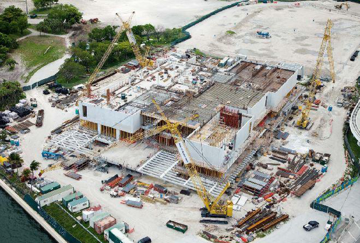
Figure 5-1: Miami Art Museum (Cobiax USA, 2013)
5.3 York University Life Science Building
York University in York, Ontario completed a new Life Science building in June 2012. The building is a 160,000 square foot (14,865m2), four-story building that includes lecture halls, classrooms, offices, and secure laboratories for biology research. The building structure is comprised of reinforced concrete columns, flat plate slabs, and shear walls. Lecture hall bays include spans over 30 feet (9m) (Blackwell Bowick, 2012).
The use of solid flat slabs for the floor plates in the building necessitated the use of drop beams, creating unwanted increases in floor-to-floor heights. The decision was made to utilize a BubbleDeck plastic voided slab system, meaning that the beams would no longer be needed and the floor-to-floor heights could remain at a desired level.
Replacing solid slabs with the voided slab system also allowed for smaller columns and foundations, as well as significantly reducing seismic forces for the building (BubbleDeck North America, 2012). BubbleDeck voided slabs also allowed the construction schedule to move at a faster pace for this project by reducing the time for slab construction.
5.4 Abuja, Nigeria Tower Hotel
In 2006, construction began on the Abuja Tower Hotel in Abuja, Nigeria. The tower consists of 22 floors that include a hotel, shopping areas, and restaurants. The plan consists of staggered rings spiraling up with an open center (Tower hotel, 2013). The architect and owner desired to have an open plan to allow for maximum use of the space. The U-Boot Beton system was used for the tower to lighten the slab, allow for minimal column use, and open the floor plan dramatically by allowing longer spans as compared to a solid slab system (U-boot Beton, 2011).
5.5 UEFA Headquarters
In early 2009, construction began on the new headquarters building for the Union of European Football Association (UEFA) in Nyon, Switzerland. A two-story parking garage was constructed adjacent to the office building. The building is circular in shape, with an opening in the middle consisting of a central courtyard, making the building's overall shape similar to a doughnut. Glass curtain walls make up the exterior walls and courtyard walls. The architect wished to use no interior columns to allow for an open work space while also wanting to minimize columns along the exterior walls to maximize visibility through the curtain walls.
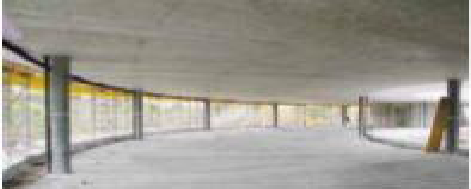
Figure 5-2: UEFA Headquarters Interior ( Cobiax Insight , 2010)
Chapter 6
Methodology
6.1 Design of Traditional Flat Slab
Size of panel=9*8
Live load =1.2kN/m
Floor finish=1 kN/m
Grade of concrete=M25
Grade of steel=fe415
Size of column =400*400
Floor to floor height of column=3.35m
L1=9000mm
L2=8000mm
Trial Depth:-
Since the depth of slab is governed by serviceabilty criteria the thickness be determined by deflection consideration based on L/d ratio.
L/d ratio for continuous slab=26
Assume required percentage of steel=0.4
Modification factor corresponding to fs=240 N/mm 2
Pt =0.4% from fig -4 clause 23.2.1,Is456:2000
α =1.3
Required depth, d= 9000 26 * 1.33 =260.27
D=260.27+20+10/2
D=290mm
d=290-10/2-20= 265mm
effective deph in transverse direction=265-10=255
Loads :-
Dead load =25*0.29*1=7.25KN/m
Live load=1.2KN/m
Floor finish =1KN/m
Total load =9.45kN/m
Factored load=1.5*9.45=14.175KN/m
By direct design method:-
Drop:-
The minimum dimention of drop,
Length of drop along long span ≤ L1/3=9/3=3m
Length of drop along short span≤L2/3=2.67m
Size of drop is conveniently selected such that it lies along the column strips.
Width of column strip minimum of (L1/2 or L2/2)=(9/2 or8/2)=4m
Provide drop of size4m*4m
Thickness of drop <thickness of slab /4 <290/4=72.5mm
Total thickness of drop =290+72.5=362.5mm=365mm
Column head :-
Diameter of column capital at top of internal column = 1 4 to 1 5 of 9+8 2
= 1 4 to 1 5 of 8.5
= 2.15 to 1.7m
Provide column capital of 2000mm,
Diameter with inclination of 45 ° ,
Size of equivalent square capital =0.89D=0.89*2000=1780mm=1.78mm
Design moment in longitudinal direction :-
Total design moment in longitudinal direction =M= wu * l 2 * ln 2 8
Ln=L1-0.89*D=9000-1780
=7220mm>0.65*9000
=7220mm>5850mm
Mo= 14.175 * 8 * 7.22 2 8 =738.92KN/m
Distribution of total design moments in longitudinal direction as panel moments :-
The division of positive and negative moment depends on the ratio ,α = ∑ kc ks
∑ k c = 2* 4 * E * I c Lc =2*(4*E* 400 * 400 3 /12 3350 ) =5.09*E*10 6 N-mm
Ks = 4*EI*s1/L*s1
=4*E*( 8000 * 365 3 12 * 9000 )
=14.41*10 6 *E N-mm
α = ∑ k c k s = 5.09 14.41
factor =1+ 1 α
=1+1/0.353
=3.83
A)Exterior panel (panel moments):-
Total negative moment at exterior support =0.65* Mo β
=0.65*738.92/3.83
=125.4KNm
Total neagative moment at interior support = 0.75 - 0.1 β * M 0
=0.75-0.1/3.83*738.92KNm
=534.89 KNm
Total positive moment at mid span=(0.63-- 0.28 β )*738.92
=411.5KN-m
B)Interior panel (panel moment):-
Total negative moment =0.65*738.92
=480.294KN-m
Total positive moment=0.35*738.93
=480.294KN-m
Distribution of longitudinal panel moment into strip moments:-
A)Exterior panel moment:-
a)Negative panel moment:-
Negative moment at exterior support is taken up by column strip =125KNm
= 125.4 4 =31.35KN-m/m
Negative panel moment of =534.89KN-m at interior support is distributed in the transverse direction as:-
Negative moment in the column strip =0.75*534.89=401.16KN-m
=401.16/4=100.29KN-m
Negative moment in middle strip =0.25*534.89=133.72KN-m
=133.72/4=33.43KN-m
b)Total positive panel moment :-
411.5KN-mis distributed in transverse direction
Positive moment in the column strip =0.6*411.5=246.9KN-m
=246.9/4=61.73KN-m
Positive moment in middle strip =0.4*411.5=164.6KN-m=164.6/4=41KN-m
B)Interior panel (strip moment):-
a)Total negative panel moment=480.294KN-m is distributed in transverse direction:-
Negative moment in column strip=0.75*480.29=360.22=360.22/4=90KN-m
Negative moment in middle strip 0.25*480.294=120.07=120.07/4=30KN-m
Total positive panel moment=258.62KN-mis distributed in transverse direction:-
Positive moment column strip0.6*258.62=155.172KNm=155.172/4=38.8KNm
b)Positive moment middle strip=0.4*258.62=103.45=103./4=25.86KN-m
Design moment in transverse direction :-
Total moment in transverse direction = Mo 2 = w u * L 1 * Ln2 2 8
Ln2=L2-0.890=8000-1780=6220mm
MO2=14.175*9*6.22 2 /8=616.95KN-m
Distribution of total design moment in transverse direction as a panel ∑kc=5.09*E*10
Ks=4*E*I*s 2 /Ls2
=4*E*(9000*365 2 /12*8000)=18.23*E*10 6
αc = ∑ Kc Ks =5.09/18.23=0.28
βc=1+ 1 αc =1+1/0.28=4.57
A)Exterior panel(panel moment):-
Total negative moment at exterior support=0.65* Mo2 β =0.65* 616.95 4.57 =87.75KNm
Total negative moment at interior support=(0.75-- 0.1 β )*Mo2
=(0.75-- 0.1 4.57 )*616.95=449.21KN-m
Positive moment in mid span=(0.63 - 0.28 β -)*Mo2=350.88KNm
B)Interior panel (panel moment):-
Total negative moment=0.65*Mo2=401.02KNm
Total positive moment=0.35*Mo2=215.93KNm
Distribution of transverse panel moment into strip moment:-
A)Exterior panel :-
a)negative moment:-
negative moment at exterior support is fully taken by column strip87.75KNm
= 87.75 4 =21.94KNm
Negative moment at 449.21KNm at interior support distributed at column strip and middle strip=
Negative moment in column strip=0.75*449.21=336.9= 336.9 4 =84.22KNm
Negative moment in middle strip=0.25*449.21=112.3= 112.3 4 =22.46KNm
b)total positive (panel moment)=350.88KNm
positive moment in column strip=0.6*350.88=210.52= 210.52 4 =52.63KNm
positive moment in middle strip=0.4*350.88=140.35= 140.35 5 =28.07KNm
B)Interior panel:-
a)Negative moment:-
negative moment in column strip =0.75*401.02=300.76= 300.6 4 =75.19KNm
negative moment in middle strip=0.25*401.02=100.25= 100.25 5 =20.05KNm
b)positive moment :-
positive moment in column strip=0.6*215.93=129.55= 129.55 4 =32.38KNm
positive moment in middle strip=0.4*215.9=86.37= 86.37 5 =17.27KNm
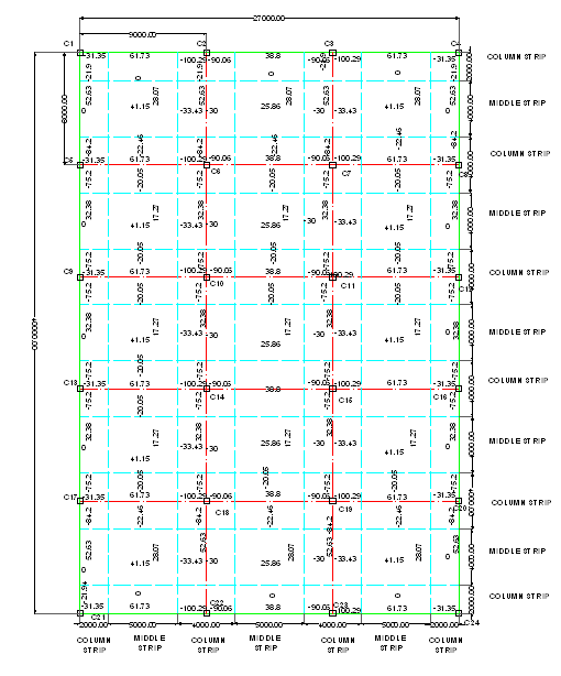
Fig 6.1 Distribution of moments in Panels
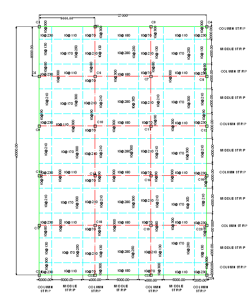
Fig 6.2 Spacing of Bars in Panels

Fig 6.3 Reinforcement Detail For exterior Panel
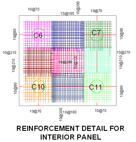
Fig 6.4 Reinforcement Detail For Interior Panel

Fig 6.5 Sectional Details For Traditional Flat Slab
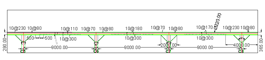
Fig.6.6 Sectional Details For Traditional Flat Slab
CHECK FOR DEPTH FOR FLEXURE:-
Mu=0.138fck*b*d 2
100.29*10 6 =0.138*25*1000*d 2
d =170.49mm
Hence safe
CHECK FOR DEPTH FOR DEFLECTION:-
Area of steel required for maximum positive moment of =61.73KN-m
= 0.5 * 25 415 *(1- 1 - 4.6 * 61.73 * 10 6 25 * 1000 * 330 2 )=532.63mm 2
Spacing = π 4 * 10 2 * 1000 532.63 =140mm c/c
Ast provided= π 4 * 10 2 * 1000 140 =561mm 2
pt % =100* Ast b * d =100* 561 1000 * 330 =0.17%
fs=0.58*415* 532.63 561 =228.53N/mm 2
from figure no 4 IS456:2000 Modification factor =α1 =1.78
Required depth = 9000 26 * 1.78 =194.47<330mm
Hence safe .
CHECK FOR SHEAR:-

Fig 6.7 Critical Section For Shear
a) Interior column:-
Check for shear around column capital :-
Effective depth of slab=255mm
Effective depth of drop =330mm
Critical perimeter for shear is a distance d 2 arround the column capital
The projection of drop beyond column capital =4000-2000/2=1000mm
Since this happens to be greater than d 2 =2000+330=2330mm
While calculating design shear the weight of the drop will also be considerd:-
Weight of drop projection below slab =25*(0.365-0.29)*1.5=2.813KN/m 2
Design shear at critical section around capital:-
VuD=14.175*(9*8— π * 2.330 2 4 )+2.813*(4*4- π * 2.330 2 4 )=960.19KN
Design shear strength of concrete = τ ' uc =K* τuc1
τuc =0.25 √ fck =0.25 25 =1.25Nmm 2
K=(0.5+βc)but < 1.0
K=(0.5+ 400 400 )=1.5<1.0
K=1
=k*τuc=1*1.25=1.25Nmm 2
Shear resistance of concrete =
Vuc= τ ' uc * pod=1.25 * ( π * 2330 ) * 330 1000 =3019.46KN>Vud
Hence safe
Check for shear around the drop:-
The critical section is ar a distance d 2 =255/2=127.27mm from the periphery of drop
Design shear at critical section.
Vud=14.175*((9*8)-(4+0.255)*(4+0.255))=763.96KNm
Shear resistance of concrete :-
Vuc=1.25 *2*(4320+4320)*320/1000=6912KN>Vud
Hence safe
6.2 Design of Flat Slab by Using Plastic Voids
Size of panel=9m*8m
Live Load =1.2 KN-m
Floor Finish =1 KN/m
Grade of steel=Fe415
Grade of concrete=M25
Size of column =400*400 mm
Floor to Floor height of column=3.35 m
L1=9000mm ,L2=8000 mm
Provide D=290 mm
Assume size of plastic void for mar=220 mm
Effective depth=290 - 10 2 - 20= 265 mm
Effective depth in transverse direction=265 - 10=255 mm
Loads-:
Number of Bubble=3*3=9
Volume of Bubble=9* 4 3 *π* .11 3 =0.0501
Effective volume=0.24 m 3
Dead Load=6 KN/m
Live load=1.2 KN/m
Floor Finish=1 KN/m
Total Load=8.2 KN/m
Factored Load=1.5*8.2=12.3 KN/m
By Direct Design Method:-
Drop:-The minimum dimension of drop.
Length of drop along long span ≤ L1 3 = 9 3 =3 m
Length of drop along short span ≤ L2 3 = 8 3 =2.67 m
Size of drop is conveniently selected such that it lies along the column strip
Width of column strip minimum of ( L1 2 or L2 2 ) = ( 9 2 or 8 2 ) =4 m
Provide drop of size=4 m*4 m
Thickness of drop < T h icknessofslob 4 < 290 4 < 72.5 mm
Total thickness of drop=290+72.5=362.5 ≅ 365 mm
Column Head:-
Diameter of column capital at top of internal column= 1 4 to 1 5 of overspan
= 1 4 to 1 5 of 9+8 2
=2.125 m to 1.7 m
Provide column capital of 2000 mm diameter with inclination of 45°
Size of equivalent square capital=0.89*2000=1780 mm=1.78 m
Design Moment in Longitudinal Direction:-
Total design moment in longitudinal direction=MD1
= Wu * L2* Ln 2 8
Where, Ln=L1 - 0.89D
=9000 - 0.89*2000
=7220 mm> 5850 mm
Mo= 12.3*8* 7.22 2 8 =641.18 KN-m
Distribution of total design moments in longitudinal direction as panel moments:-
The division of positive and negative moment depends on the ratio αc= ∑Kc Ks
∑Kc=2*( 4*E * Ic Lc )
=2* (4*E * 400* 400 3 12 ) 3350
=5.09E* 10 6 N-mm
Ks= 4E * Is1 Ls1
=4E* ) 9000
=14.41* 10 6 E N-mm
∝c= ∑Kc Ks = 5.09 14.41 =0.353
Factor=1 + 1 αc =1+ 1 0.353 =3.83
A)Exterior panel (panel moments):-
Total negative moment at exterior support=0.65* Mo1 β
=0.65* 641.18 3.83
=108.81 KN-m
Total negative moment at interior support =(0.75 - 0.1 β )Mo1
=(0.75 - 0.1 3.83 )*64.18
=464.14 KN-m
Total positive moment at mid span=(0.63 - 0.28 β )Mo1
=(0.63 - 0.28 3.83 )*641.18
=357.07 KN-m
B) Interior panel (Panel moment):-
Total negative moment=0.65*641.18
=416.76 KN-m
Total positive moment =0.35*M0
=0.35*641.18
=224.41 KN-m
Distribution of longitudinal panel moment into strip:-
A) Exterior panel (Panel moment):-
a) Negative panel moment:-
Negative moment at exterior support is taken up by column strip=108.81 KN-m
= 108.81 4
=27.2 KN-m/m
Negative panel moment of 464.14 KN at interior support is distributed in the transverse direction as,
Negative moment in the column strip=0.75*464.14
=348.11 KN-m
= 348.11 4
=87.03 KN-m/m
Negative moment in middle strip=0.25*464.14
=116.04 KN-m/m
= 116.04 4
=29 KN-m/m
b) Total positive panel moment =357.07 KN-m
Positive moment in the column strip =0.6*357.07
=214.24 KN-m
= 214.24 4
=53.56 KN-m/m
Positive moment in the middle strip =0.4*357.07
=142.83 KN-m
= 142.83 4
=35.71 KN-m/m
B) Interior panel (strip moment):-
Total negative moment =416.76 KN-m
Total positive moment=224.41 KN-m
a) Total negative panel moment:-
Negative moment in the column strip =0.75*416.76
=312.57 KN-m
= 312.57 4
=78.14 KN-m/m
Negative moment in the middle strip =0.25*416.76
=104.19 KN-m
= 104.19 4
=26.05 KN-m/m
b) Total positive panel moment:-
Positive moment in the column strip =0.6*224.41
=134.65 KN-m
= 134.65 4
=33.66 KN-m/m
Positive moment in the middle strip =0.4*224.41
=89.76 KN-m
= 89.76 4
=22.44 KN-m/m
Design Moment in Transverse Direction:-
Total moment in transverse direction=Mo2= Wu * L1* Ln2 2 8
Where, Ln2=L2 - 0.89D
=8000 - 1780
=6220 mm
= 12.3*9* 6.2 2 8
=531.91 KN-m
Distribution of total design moment in transverse direction as a panel moments:-
∑Kc=5.09*E* 10 6 N-mm
Ks= 4*E( 9000* 365 3 12 ) 8000
=18.23*E* 10 6 N-mm
αc= ∑Kc Ks = 5.09 18.23 , αe=0.28
β=1 + 1 ∝e =1+ 1 0.28 , β=4.57
A)Exterior panel (Panel moment):-
Total negative moment at exterior support =0.65* Mo2 β
= 0.65*531.91 4.57
=75.65 KN-m
Total negative moment at interior support =(0.75 - 0.1 β )*Mo2
= (0.75 - 0.1 4.57 )*531.91
=387.29 KN-m
Positive moment at mid span= (.63 - 0.28 β )*Mo2
= (0.63 - 0.28 4.57 )*531.91
=302.51 KN-m
B) Interior panel (Panel moment):-
Total negative moment =0.65*Mo2
=0.65*531.91
=345.74 KN-m
Total positive moment=0.35*531.91 =186.16 KN-m
Distributing transverse panel moment into strip moment:
A)Exterior panel:-
a) Negative moment:-
Negative moment at exterior support
fully taken by column strip =75.65 KN-m
= 75.65 4
=18.91 KN-m/m
Negative moment of 387.29 KN-m at interior support is distributed in column strip
Negative moment in column strip=0.75*387.29
=290.47 KN-m
= 290.47 4
=72.62 KN-m/m
Negative moment in middle strip =0.25*387.29
=96.82 KN-m
= 96.82 5
=19.36 KN-m/m
b) Total positive panel moment=302.5 KN-m
Positive moment in column strip=0.6*302.5
=181.5 KN-m
= 181.5 4
=45.375 KN-m/m
Positive moment in middle strip =0.4*302.5
=121 KN-m
= 121 5
=24.2 KN-m/m
B) Interior panel (Strip moment):-
a) Negative moment:-
Negative moment in column strip =0.75*345.74
=259.3 KN-m
= 259.3 4
=64.83 KN-m/m
b) Positive moment:-
Positive moment in column strip=0.6*186.16
=111.7 KN-m
= 111.7 4
=27.92 KN-m/m
Positive moment in middle strip =0.4*186.16
=74.464 KN-m
= 74.464 5
=14.89 KN-m/m
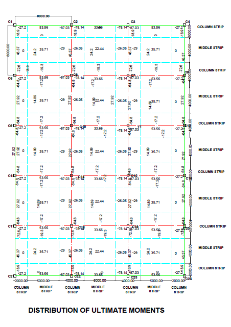
Fig 6.8 Distribution of Ultimate Moment
Reinforcement calculation :-
Ast= 0.5*25 415 [1- 1- 4.6*95.6* 10 6 25*1000* 330 2 ] *1000*330=656.51 mm 2
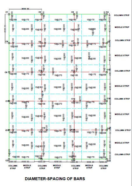
Fig 6.9 Spacing of Bars in Panels

Fig 6.10 Reinforcement Detail For Exterior Panel

Fig 6.11 Reinforcement Detail For Interior Panel
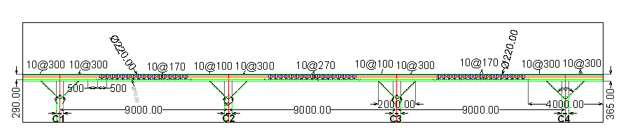
Fig 6.12 Sectional Details Of Plastic Voided Slab

Fig. 6.13 Sectional Details Of Plastic Voided Slab
Check for depth for flexure:-
Mu=75.6 KN-m
Required d= Mu 0.138*Fck * b
= 75.6* 10 6 0.138*25*1000
=148 mm
Hence safe
Check for depth for deflection:-
Area of steel required for minimum positive moment=53.56 KN-m
Area of steel(required)=460.4 mm 2
Spacing =170 mm
Area provided = π 4 * 10 2 * 1000 170 =462 mm 2
Pt% = 100*462 1000*330 =0.14 %
Fs =0.58*Fy* Astreq Astprov
=0.58*415* 460.4 462
=240 N/ mm 2
Modification factor =1.85 (From fig 4 IS456:2000 page no. 38)
Required depth = 9000 2.6*1.85 =187.11 mm < 330 mm
Hence safe
Check for shear:-
Fig 6.14 Critical Section For Shear
a)Interior column:-
Check for shear around column capital:-
Effective depth of slab =255 mm
Effective depth of drop=330mm
Critical perimeter for shear is a distance d 2 around the column capital
The projection of drop beyond column capital=(4000 - 2000 )/2
=1000 mm
Since this happens to be greater than=d/2=2000 + 330=2330 mm
While calculation design shear, the weight of the drop will be also considered.
Weight of drop projection below slab=25*(0.365 - 0.29 )*1.5
=2.81 KN/ m 2
Design shear at critical section around capital:-
Vud=12.3*(9*8 - π * 2.330 2 4 )
=833.15 KN
Design shear strength of concrete:-
τ ' uc=k * τuc
Where, τuc=0.25* Fck =0.25* 25 =1.25 N/ mm 2
K= (0.5 +βc)<1.0
= (0.5 + 400 400 )
=1.5 <1.0
Hence take k=1.0
τ ' uc=1*1.25
=1.25 N/ mm 2
Shear resistance of concrete =Vuc= τ ' uc * pod
=1.25* π * 2330* 330 1000
=3019.46 KN > (Vud=833.15 KN)
Hence safe
Check for shear around the drop:-
The critical section is at a distance d/2 < 255 2
=127.5 mm from the perimeter of drop
Design shear at critical section:-
Vud=12.3*{9*8 - ( 4+0.32 ) * (4+0.32)} =656.05 KN
Shear resistance of concrete:-
Vuc=1.25*2*(4320 +4320)* 255 1000
=5508 KN >(Vud=656.05 KN)
Hence safe
6.3 DESIGN OF TRADITIONNAL FLAT SLAB USING EXCEL SHEET

Fig.6.15-DEPTH OF SLAB AND DROP

Fig.6.16-STRIP MOMENTS AND SPAECING OF BARS

Fig.6.17-CHECKS
6.4 DESIIGN OF PLASTIC VOIDED SLAB USING EXCEL SHEET

Fig.6.18-DEPTH OF SLAB AND DROP

Fig.6.19-STRIP MOMENT AND SPACING OF BARS

Fig.6.20-CHECKS
6.5 ESTIMATION OF STEEL FOR TRADITIONAL FLAT SLAB:-

Fig 6.21 Distribution of Zones In Total Slab
| DESCRIPTION | NO. OF SIMILAR ZONE | NUMBERS OF BARS | LENGTH | 10MM | TOTAL LENGTH |
| C1,C2,C5,C6 | | | | | |
| Z0NE 1,7,71,77 | 4 | | | | |
| MAIN | | 16 | 4.5 | 72 | 288 |
| DIST | | 16 | 4.5 | 72 | 288 |
| ZONE 2,6,72,76 | 4 | | | | |
| MAIN | | 28 | 6 | 168 | 672 |
| ZONE 3,5,73,75 | 4 | | | | |
| MAIN | | 46 | 5 | 230 | 920 |
| DIST | | 18 | 4.5 | 81 | 324 |
| ZONE 8,14,64,70 | 4 | | | | |
| DIST | | 25 | 5 | 125 | 500 |
| Z0NE 9,13,65,69 | 4 | | | | |
| MAIN | | 21 | 6 | 126 | 504 |
| DIST | | 21 | 5 | 105 | 420 |
| zone 10,12,66,68 | 4 | | | | |
| MAIN | | 18 | 5 | 90 | 360 |
| DIST | | 28 | 5 | 140 | 560 |
| ZONE 15,21,57,63 | 4 | | | | |
| MAIN | | 18 | 4.5 | 81 | 324 |
| DIST | | 39 | 5 | 195 | 780 |
| ZONE 16,20,58,62 | 4 | | | | |
| MAIN | | 31 | 6 | 186 | 744 |
| DIST | | 21 | 5 | 105 | 420 |
| ZONE 17,19,59,61 | 4 | | | | |
| MAIN | | 51 | 5 | 255 | 1020 |
| DIST | | 43 | 5 | 215 | 860 |
| ZONE 4,74 | 2 | | | | |
| MAIN | | 18 | 6 | 108 | 216 |
| ZONE 11,67 | 2 | | | | |
| MAIN | | 18 | 6 | 108 | 216 |
| DIST | | 21 | 5 | 105 | 210 |
| ZONE 18,60 | 2 | | | | |
| MAIN | | 20 | 6 | 120 | 240 |
| DIST | | 21 | 6 | 126 | 252 |
| ZONE 22,28,36,42,50,56 | 6 | | | | |
| DIST | | 16 | 5 | 80 | 480 |
| ZONE 23,27,37,41,51,55 | 6 | | | | |
| MAIN | | 21 | 6 | 126 | 756 |
| DIST | | 21 | 5 | 105 | 630 |
| ZONE 24,26,38,40,52,54 | 6 | | | | |
| MAIN | | 18 | 5 | 90 | 540 |
| DIST | | 18 | 5 | 90 | 540 |
| ZONE 29,35,43,49, | 4 | | | | |
| MAIN | | 18 | 4.5 | 81 | 324 |
| DIST | | 36 | 5 | 180 | 720 |
| ZONE 30,34,44,48 | 4 | | | | |
| MAIN | | 31 | 6 | 186 | 744 |
| DIST | | 21 | 6 | 126 | 504 |
| ZONE 31,33,45,47 | 4 | | | | |
| MAIN | | 51 | 5 | 255 | 1020 |
| DIST | | 40 | 5 | 200 | 800 |
| ZONE 25,39,60 | 3 | | | | |
| MAIN | | 18 | 6 | 108 | 324 |
| DIST | | 21 | 5 | 105 | 315 |
| ZONE 32,46 | 2 | | | | |
| MAIN | | 20 | 6 | 120 | 240 |
| DIST | | 21 | 5 | 105 | 210 |
| TOTAL ZONE | 77 | | | | 18265 |
6.6 ESTIMATION OF CONCRETE OF TRADITIONAL FLAB SLAB
| DESCRIPTION | LENGTH | WIDTH | DEPTH | QUANTITY | |
| TOTAL SLAB | 44 | 31 | 0.365 | 497.9 | Cu-m |
| Sr. No. | Description of item | Unit | Quantity | Rates | Amount(Rs) |
| 1 | CONCRETE:- Providing and laying in position in situ plain cement concrete as per IS 456:2000 for slab. The rate shall include bailing out water, manually centering, shuttering, compacting by vibrator and curing. GRADE:M25 | Cu.m | 497.86 | 7125 | 3547253/- |
| 2 | REINFORCEMENT 0F STEEL:- Providing and fixing in position reinforcement of 10mm diameter for RCC slab as per detail design and drawing and schedules including cutting, bending,hooking the bars, binding with wires or tack welding and supporting as required completed For HYSD steel bars | Tonne | 11.275 | 72000 | 811800/- |
| | TOTAL | | | | 4359053/- |
6.7 ESTIMATION OF STEEL IN PLASTIC VOIDED SLAB
Fig 6.22 Distribution of Zones in Total Slab
| DESCRIPTION | NO. OF SIMILAR ZONE | NUMBER OF BARS | LENGTH | 10MM | TOTAL LENGTH |
| C1,C2,C5,C6 | | | | | |
| Z0NE 1,7,71,77 | 4 | | | | |
| MAIN | | 16 | 4.5 | 72 | 288 |
| DIST | | 16 | 4.5 | 72 | 288 |
| ZONE 2,6,72,76 | 4 | | | | |
| MAIN | | 28 | 6 | 168 | 672 |
| ZONE 3,5,73,75 | 4 | | | | |
| MAIN | | 46 | 5 | 230 | 920 |
| DIST | | 18 | 4.5 | 81 | 324 |
| ZONE 8,14,64,70 | 4 | | | | |
| MAIN | | 25 | 5 | 125 | 500 |
| Z0NE 9,13,65,69 | 4 | | | | |
| MAIN | | 21 | 6 | 126 | 504 |
| DIST | | 21 | 5 | 105 | 420 |
| zone 10,12,66,68 | 4 | | | | |
| MAIN | | 18 | 5 | 90 | 360 |
| DIST | | 28 | 5 | 140 | 560 |
| ZONE 15,21,57,63 | 4 | | | | |
| MAIN | | 18 | 4.5 | 81 | 324 |
| DIST | | 39 | 5 | 195 | 780 |
| ZONE 16,20,58,62 | 4 | | | | |
| MAIN | | 30 | 6 | 180 | 720 |
| DIST | | 21 | 5 | 105 | 420 |
| ZONE 17,19,59,61 | 4 | | | | |
| MAIN | | 51 | 5 | 255 | 1020 |
| DIST | | 43 | 5 | 215 | 860 |
| ZONE 4,74 | 2 | | | | |
| MAIN | | 18 | 6 | 108 | 216 |
| ZONE 11,67 | 2 | | | | |
| MAIN | | 18 | 6 | 108 | 216 |
| DIST | | 21 | 5 | 105 | 210 |
| ZONE 18,60 | 2 | | | | |
| MAIN | | 20 | 6 | 120 | 240 |
| DIST | | 21 | 5 | 105 | 210 |
| ZONE 22,28,36,42,50,56 | 6 | | | | |
| DIST | | 16 | 5 | 80 | 480 |
| ZONE 23,27,37,41,51,55 | 6 | | | | |
| MAIN | | 21 | 6 | 126 | 756 |
| DIST | | 20 | 5 | 100 | 600 |
| ZONE 24,26,38,40,52,54 | 6 | | | | |
| MAIN | | 18 | 5 | 90 | 540 |
| DIST | | 18 | 5 | 90 | 540 |
| ZONE 29,35,43,49, | 4 | | | | |
| MAIN | | 18 | 4.5 | 81 | 324 |
| DIST | | 36 | 5 | 180 | 720 |
| ZONE 30,34,44,48 | 4 | | | | |
| MAIN | | 31 | 6 | 186 | 744 |
| DIST | | 21 | 5 | 105 | 420 |
| ZONE 31,33,45,47 | 4 | | | | |
| MAIN | | 50 | 5 | 250 | 1000 |
| DIST | | 40 | 5 | 200 | 800 |
| ZONE 25,39,60 | 3 | | | | |
| MAIN | | 18 | 6 | 108 | 324 |
| DIST | | 21 | 5 | 105 | 315 |
| ZONE 32,46 | 2 | | | | |
| MAIN | | 20 | 6 | 120 | 240 |
| DIST | | 21 | 5 | 105 | 210 |
| TOTAL ZONE | 77 | | | | 18065 |
6.8 ESTIMATION OF CONCRETE IN PLASTIC VOIDED SLAB
| DESCRIPTION | NUMBER | LENGTH | WIDTH | DEPTH | QUANTITY | |
| CONCRETE:- | | | | | | |
| TOTAL SLAB | 1 | 44 | 31 | 0.365 | 497.86 | Cu-m |
| DEDUCTION:- | | | | | | |
| PLASTIC BALLS | 8820 | VOL=(4/3)*π*0.11^(3)=0.005575 | 49.172 | Cu-m | ||
| ACTUAL QUANTITY | | | | | 448.688 | Cu-m |
| Sr. No. | Description of item | Unit | Quantity | Rates | Amount(Rs) |
| 1 | CONCRETE:- Providing and laying in position in situ plain cement concrete as per IS 456:2000 for slab. The rate shall include bailing out water, manually centering, shuttering, compacting by vibrator and curing. GRADE:M25 | Cu.m | 448.688 | 7125 | 3196902/- |
| 2 | REINFORCEMENT 0F STEEL:- Providing and fixing in position reinforcement of 10mm diameter for RCC slab as per detail design and drawing and schedules including cutting, bending, hooking the bars, binding with wires or tack welding and supporting as required completed For HYSD steel bars | Tonne | 11.151 | 72000 | 802872/- |
| 3 | PLASTIC FORMERS/BALLS:- Plastic void formers of HDPE (High Density Polyethylene). | No's | 8820 | 7 | 61740/- |
| | TOTAL | | | | 4061514/- |
Chapter 7
Result And Conclusion
7.1 Result
(1)Comparison of Longitudinal and Transverse moments for various spans between Traditional Flat Slab and Plastic Voided Slab. Using Fe 415 Grade Steel and M25 Grade Concrete.
| Sr.No | Span | Traditional Flat Slab | Plastic Voided Slab | ||
| Longitudinal Moment(KN-m) | Transverse Moment(KN-m) | Longitudinal Moment(KN;m) | Transverse Moment(KN-m) | ||
| 1 | 9mx8m | 885.53 | 739.37 | 660.38 | 551.38 |
| 2 | 9mx7m | 774.84 | 520.74 | 577.83 | 388.34 |
| 3 | 8mx7m | 529.05 | 425.84 | 409.42 | 329.55 |
| 4 | 7mx5m | 332.93 | 210.90 | 267.31 | 169.33 |
(2)Comparison of Area of steel Reinforcement for various spans between Traditional Flat Slab and Plastic Voided Slab. Using Fe 415 Grade Steel and M25 Grade Concrete
| SR.No | Span | Traditional Flat Slab | Plastic Voided Slab |
| | | Area of steel(mm 2 ) | Area of steel(mm 2 ) |
| 1 | 9mx8m | 11169.88 | 8203.43 |
| 2 | 9mx7m | 9970.14 | 7330.05 |
| 3 | 8mX7m | 7650.52 | 6074.67 |
| 4 | 7mX5m | 8431.82 | 6452.02 |
(3)Comparison of construction COST of slab between Traditional Flat Slab and Plastic Voided Slab. Using Fe 415 Grade Steel and M25 Grade Concrete
FOR PANEL SIZE 9mx8m,
a)FOR TRADITIONAL FLAT SLAB,
COST=Rs. 4359053/-
b)FOR PLASTIC VOIDED SLAB,
COST=Rs. 4061514/-
PROFIT=Cost of Traditional Flat Slab – Cost of Plastic Voided Slab
=4359053-4061514
PROFIT = Rs.297539/-
7.2 Conclusion
The benefits of using plastic voided slabs rather than solid slabs are greater for larger spans. Smaller spans do not require substantially thick slabs, therefore only small voids can be utilized and minimal savings are achieved. Larger spans are capable of using larger voids that greatly reduce the overall weight of the slab while meeting load capacity requirements.
Construction of plastic voided slabs requires more steps than solid slabs, but the construction process is not significantly more complicated. For bays of the same size, plastic voided slabs typically require less reinforcement. The only major change is placement of the plastic void formers. The void formers are placed above the bottom layer of reinforcement and are usually contained in a cage of very thin steel bars. The cage of void formers is typically constructed at the manufacturer's facility and shipped to the construction site, allowing for quick placement of the void formers and minimal changes to the construction schedule compared to solid slab systems.
REFERENCES
1. Lancaster L. C. (2005). Concrete Vaulted Construction in Imperial Rome: Innovations in Context // Cambridge University Press. 2005. Pp. 6-10.
2. A. Churakov.. Biaxial hollow slab with innovative types of voids
3. COREY J MIDKIFF B.S., Kansas State University, 2013, PLASTIC VOIDED SLAB SYSTEMS: APPLICATIONS AND DESIGN
4. BubbleDeck [web source] URL: http://www.BubbleDeck.com
5. Cobiax [web source] URL: http://www.cobiax.com
6. U-boot [web source] URL: http://www.daliform.info/USB/download/referenze/Uboot_reference.
7. Schnellenbach-Held M., Ehmann S., Pfeffer K. (1998). BubbleDeck - New Ways in Concrete Building. Technische Universität Darmstadt, DACON. 1998. Vol. 13. Pp. 93-100.
8. Prof. Kleinman. (1999). BubbleDeck Report from A+U Research Institute. Eindhoven University of Technology. 1999. Pp. 14-15.
9. Koning B. (1998). BubbleDeck Test Report. The Netherlands. 1998. Pp. 3-9.
10. Report of BubbleDeck from Technische Universitaet in Cottbus. 1999. Pp. 10-12.
11. BubbleDeck Report from Technical University of Denmark. 2003. Pp. 9-11.
12. Optimising of Concrete Constructions. The Engineering School in Horsens / Denmark. 2000. Pp. 18-19
13. Centre for Civil Engineering Research and Codes (CUR), Recommendation 86. Pp. 4-12
14. Punching Shear Strength of BubbleDeck. The Technical University of Denmark. 2002. Pp. 5-8.
15. Designing Parameters As Per IS 456:2000
16. S.R. Karve, Reinforced Concrete Design
Design of Flat Slab Using Is 456 Excel
Source: http://practicalcivilworks.blogspot.com/2017/04/plastic-voided-slab-design-by-is-456.html
0 Response to "Design of Flat Slab Using Is 456 Excel"
Post a Comment